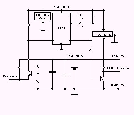
 The schematic of the circuit.
Robs Stupid Computerized Ignition Timing Controller
November 2, 2001. After I my distributor siezed, and I got another, I forgot to get the advance parts out of the old old when I gave them the old one in return. The last 2 distributors I have bought have had the newer 18/21 degree advance mechanisms, which are useless on an older car. More suited to a truck, which is probably what most 390s on the road are nowadays
My car, and most old cars, I would imagine, like to have almost 10 degrees of timing advance at idle, and about 36 degrees max at upper rpms. The advance mechanism in the distributor is what sets the range of advance.
My distributor was originally setup with a 13 degree advance mechanism, which gives a range of 26 degrees advance between idle and redline. This is nearly perfect for my car to change the timing from 10 to 36 as it is revved up.
With the distributor advance range set to 18 degrees, the only way to keep from pinging at upper RPMs is to retard the initial timing to nearly 0 degrees, which makes nearly no power at idle. Most of my gocarts take off faster than my car when it is setup like this. This just wont do.
I pondered my options for awhile. I could try to find an original 13 degree advance unit, or spend $200 on an aftermarket distributor which would give more flexibility than the original distributor, or go all out and buy a crank triggered ignition, complete with timing controller box.
April 2, 2002. The computerized setup sounded like the best idea, until I started checking prices. All of a sudden, I had a silly idea: why not build my own computerized timing controller which I can customize however I want.
If I build it myself, I can make it so I can change between different timing curves with the push of a button and make it do all kinds of cool stuff too, and save at least a thousand dollars compared to what the aftermarket system with less flexibility would cost.
The first thing I did was install an MSD 6A, not necessarily for the multiple spark benefit, which couldnt hurt, but it takes less than half an amp to drive and MSD box, compared to around 10 Amps to drive the coil directly. Not having to control nearly as much current makes the output stage of the timing controller much simpler and the overall board much smaller.
For really bored people, a page of numbers and stuff"
April 22, 2002. I drove the car to work today with the timing controller running the show. It worked great, smooth power throughout the RPM range, with no pinging! I know I can get more out of it by tweaking the advance curves some more, but it is way better already. The only flaw is a slight stumble if I punch it at idle, which may be timing related, or a bug in transitioning from idle mode.
The next step is to add the LCD interface and some buttons to make possible to configure it inside the car. Once I get the interface done, I have some leftover solid state vacuum transducers from another project that I can interface with the controller to map the vacuum advance as well.
June 13, 2002. Making the controller was the easy part. Since I wanted to install a PC In My Car to play mp3s anyway, I figured I should do that first to make it easier to monitor what the controller is doing, and having a laptop installed all the time made it quicker to check new versions of the interface programs, since I didnt have to disconnect the controller, take it inside, hook it to a PC, etc, to make every little change.
November 7, 2002. Of course, the controller doesnt need the PC connected to work, it only adds to the functionality. The windows program has several functions:
1. The main function of the program is to allow adjusting the timing curve. Having the laptop connected allows adjusting timing curve while the car is running. It is possible to do on the freeway, but I wouldnt suggest it unless you have a helper.
2. It has a real time data monitor that shows RPM and amount of advance in real time in a cool graphical display.
3. The PC program takes the timing info and logs it to a file 10 times per second that can be recalled in a neat display that can be scrolled and zoomed later to analyze 0-60 times, etc.
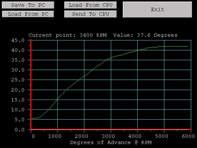 A screenshot of the timing adjustment screen
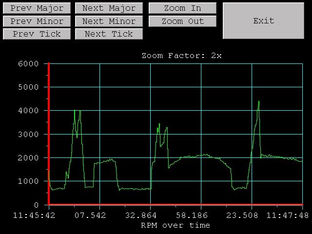 A screenshot of the log review screen
Below is a pic of the ignition monitor screen running on the display in my dash. It is showing 8 degrees of timing, max RPM of 661, and current speed of 612 RPM. The CPU board on the left is the ignition computer, and the one on the right makes the laptop think that an old IR remote I had laying around is a mouse.
I plan on installing the new board in my 68 Scout, which doesnt have an MSD or PC in it :). I also dont want to modify the distributor, since it is relatively rare. To accomplish this, there must be a couple changes to the board.
The new board will be able to drive the coil directly, which will remove the need for the MSD box. It will still be able to drive an MSD or other coil driver box, it will just be able to do it by itself for nearly stock install.
 Spark plug opened to about .200 (from normal .040)
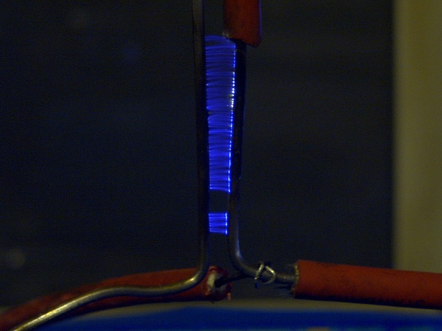 Spark can jump almost half an inch (.500)!!!
My son and I had a bunch of fun playing with the spark circuit. We found that most candy will burn if exposed to high voltage!!! We spent several hours welding candy pieces together. How stupid is that?
To make it able to be used without modifying the distributor, there is a mode that allows relative timing adjustment, as opposed as absolute control. This allows setting the normal timing on the motor to a conservative value, like what would be used for emissions. In this mode, the controller would provide additional advance in an RPM dependent way. For example, the advance springs in my Scout are worn pretty bad, so when the timing is retarded for emissions, there is little power above idle, but is nearly right in mid RPM range, and just right in the upper range. In modify mode, I can dial in 5 EXTRA degrees of timing at idle, tapering to a couple degrees in the middle, to no extra in the upper range. An additional benefit is that a flick of a switch sets it back to normal. This way it is easy to tell the benefits.
The install for the new board in relative mode can be done in 1 minute. It will involve removing the wire that goes from the points to the coil, connecting the wire to the controller, then connecting the controller to the coil, and connecting power and ground to the controller board. Piece of cake.
There will be an optional board with an LCD display and some buttons that plugs into the controller the same way the PC does that allows the same functionality. This will allow adjustment of the timing while it is running and displaying RPM and timing data in real time for those without access to a laptop.
Later, if there is enough demand, I might make a different plugin board for logging data to a memory card that can be downloaded to a computer at a later time for viewing. This allows the data analyzing function for those without a laptop.
November 9, 2002. I have at least 3 dozen people trying to get me to build one for them, but I wont sell anything until it is at least nearly perfect. It will be about a month before I start taking orders. If you are interested, Send me an email, and tell me whether you would like the bare version that requires a PC to setup, or would like options like the LCD interface or the data logging interface.
Im working on a graphic that shows the connections better. Soon, very soon.
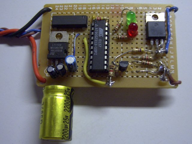 Here is a the prototype, it is ugly since there were a couple things I had to change, but it works great
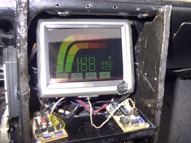 A pic of the monitor screen
Leave a Comment